KLA Instruments’ comprehensive portfolio of Optical Profiler products, software, analysis, services and expertise is designed to help scientists, researchers and engineers address their toughest measurement challenges in the fields of geochronology.
Nano Technology Solutions is the exclusive distributor of KLA Instruments and supplies, installs, supports surface metrology products and accessories across Australia and New Zealand.
Contact us to discuss your specific requirements or objectives regarding metrology for applications in geochronology.
Metrology in Laser-based Geochronology Workflows
In situ LA-(U–Th–Sm)/He dating (Zircon and Apatite)
In conventional (U-Th)/He dating, individual grains undergo microscopy observation for characterising dimensions, morphology, deformations, etc. This is followed by ⁴He extraction, and acid dissolution for parent isotope measurements, before age calculations are done. These last steps are limited by the inability to avoid inclusions from neighbour sites, effects of crystallographic defects, alpha ejection errors, etc. They also involve long processing times and safety risks1.
These constraints, combined with improvements in laser ablation techniques, have pushed researchers toward in situ laser-based analytical methods to obtain age information at higher spatial resolution, faster throughput, and with fewer destructive sample preparation steps.
Laser ablation (LA) itself provides a highly controlled method of material removal. It extracts helium and parent isotopes from polished mineral grains using UV excimer lasers (e.g., 193 nm), creating shallow pits (typically 10-20 μm wide, <2-20 μm deep) with “top-hat” profiles2.
A major advantage of in situ (U–Th)/He is that it targets defect-free zones, eliminates alpha correction, increases productivity, and improving worker safety by avoiding dissolution steps. It also enables double-dating (U-Pb/(U-Th)/He) for provenance, recycling, and exploration studies.
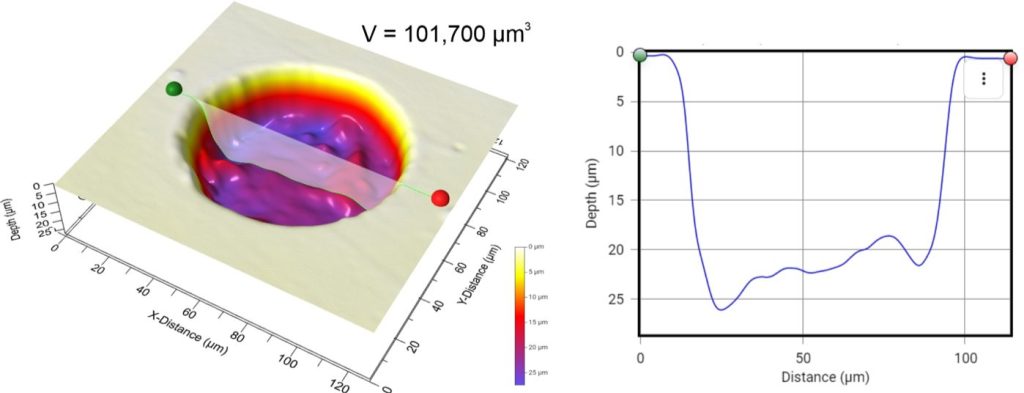
But in this approach we depend on one crucial parameter from the study of ablation pit morphology: the pit volume. It is required convert measured ⁴He into concentration, enabling correct age normalisation and thermal history reconstruction.
Source: Evans et.al., J. Anal. At. Spectrom., 2015, 30, 1636
Double dating: integrating U–Pb and (U–Th–Sm)/He on single crystals
Researchers have also developed new analytical systems for rapid, automated in situ U–Pb and (U–Th–Sm)/He double dating of zircon2, integrating multiple instruments such as an excimer laser equipped with an ultra-high vacuum (UHV) cell, a ⁴He mass spectrometer and an ICP-MS.
Double dating is useful for sediment provenance and recycling studies, and exploration applications (e.g., diamond exploration) where thermal processes are indicative of prospectivity.
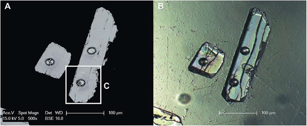
In these workflows, zircon surfaces are polished and characterised using microscopy methods to reveal internal structures that could impact pit volume measurement and to identify suitable ablation targets.
Different helium extraction strategies exist2, including:
- a small pit for helium extraction followed by a larger pit for U and Th, or
- wide, shallow ⁴He pits followed by narrower, deeper ablation for U, Th, Sm, Pb (+trace elements).
In practice, helium pits are often shallow (commonly described as having flat bottoms), and pit geometry is deliberately designed to make volume measurement easier.
How Pit Topography Affects Volume Measurement Accuracy
The general workflow in (U–Th–Sm)/He thermochronology and LA-ICP-MS based dating techniques is:
Polish and image grains optically → Ablate shallow He pit → Measure pit volume → Ablate again for parent isotope measurements.
Here there is a recurring technical requirement which is the ability to measure laser ablation pit geometry and volume accurately.
1. Small pits are analytically desirable, but harder to characterise
One study notes that increasing pit volumes makes it difficult to study and reconstruct thermal histories from in situ (U–Th–Sm)/He data, particularly for small grains3.
Larger pits can integrate regions affected by helium ejection and reduce the number of pits that can be placed on a single grain. As a result, future investigations recommend analysing large grains and keeping pit volumes as small as possible, creating a demand for high-precision volume measurements for pits of smaller sizes.
2. Pit location, grain geometry, and interpretation constraints
Measuring grain size and geometry and the laser spot position relative to the grain rim is essential for correctly interpreting in situ (U–Th–Sm)/He dates.
While these can be easily determined in the horizontal plane with optical microscopy, estimating pit location in the vertical direction is difficult, making 3D metrology a necessity.
3. Surface roughness adds uncertainty
During routine in situ dating, additional uncertainty is introduced by the roughness of the polished zircon surface (usually reported to be 5–10 nm in amplitude). This surface roughness can add approximately 2% uncertainty to volume estimations.
4. Pit morphology may deviate from ideal shapes
Shallow pits are often described as having a well-defined “top-hat” cylindrical geometry, which is ideal for accurate volume determination. However, during ablation, elongated positive structures protruding from the pit base may occur, especially where pit depth exceeds a few microns. This is potentially due to non-linear growth of surface irregularities initiated by scattering of light out of the irradiated beam by microfracture surfaces. If undetected, such structures can affect fractionation and signal intensity, introducing 1-3% volume uncertainties, thereby reducing the accuracy of age determinations2.
This is one reason detailed examination of target grains using multiple microscopy methods and applying appropriate uncertainties to pit volumes remains important, particularly when analysing grains with defects such as fractures.
Common Approaches in Pit Volume Measurement
Because pit volume is essential, several measurement approaches are used depending on pit depth, geometry, and available instruments.
Confocal Laser Scanning Microscopy (CLM) is generally used to measure pits deeper than a few microns. Confocal images are obtained by scanning through the z-axis using a pinhole corresponding to a fixed optical slice thickness. These optical sections are combined into a 3D image stack. Reported precision can be approximately 1% for repeatedly measured well-defined pits but the method is difficult for deeper pits with steep side walls. Grain geometry and rim-relative pit positioning also require vertical profiling beyond basic optical microscopy.

Atomic Force Microscopy (AFM) is commonly used for shallow pits (~10 μm). It uses a sharp mechanical probe attached to a flexible cantilever to scan pit topography and generate a 3D surface map. Pit volumes are calculated from multiple randomly selected pits per crystal using image processing software (e.g., MATLAB), and the uncertainties in volume are reported to be around 2–3%4. AFM is also inherently a contact technique, and can be slower or less practical for routine, high-throughput pit metrology on diverse materials.

Why Zeta Optical Profilers Are Ideal for Geochronology
3D Optical profilers are increasingly becoming critical components of modern geochronology labs. They enable non-contact, high-resolution 3D topography mapping, making them especially suitable to characterise ablation pits created by excimer lasers where pit shape, steep walls, or surface roughness introduce systematic uncertainties into age calculations.
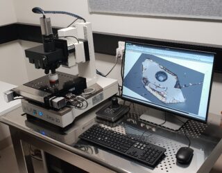
KLA’s Zeta-20 3D Optical Profiler is a Benchtop system powered by ZDot™ technology and multi-mode optics. It is designed to measure samples with low and high reflectances, and smooth and rough textures, suitable for studying geological materials and polished mineral mounts.
Zeta profilers offer a compelling combination of:
- Non-contact 3D measurement,
- High vertical resolution for steep or high aspect ratio features,
- Wide-area interferometric capability,
- Roughness and defect inspection support,
- Practical lab-friendly form factor and workflow efficiency.
Vertical resolution and high aspect ratio measurement
Compared to CLM, one of the strongest technical motivations to use Zeta profilers is the ability to measure step heights from sub-nanometre to millimetre scales in high aspect ratio features, with high vertical resolution (2–13 nm), without pinhole constraints. This can reduce volume measurement errors below 0.5%, improving the accuracy of dating results.
White light interferometry for wide-area step height measurements
Zeta profilers also provide white light interferometry for wide-area step height measurements with nm-level z-resolution, making them useful for both pit measurement and broader surface characterisation.
Measuring pit bottom roughness and surface condition
Because pit volume estimation can be affected by roughness at the pit base and surrounding polished surface, the ability to measure 3D roughness across smooth (sub-nanometre) and rough (hundreds of microns) surfaces enables a more precise characterisation of pit geometry.
Defect inspection and pre-ablation surface characterisation
Compared to AFM, Zeta profilers use a non-contact process that also features faster wide-area mapping and automated >1 μm defect detection, which can support pre-ablation characterisation steps such as identifying zones, defects, or surface issues that could impact pit geometry.
Practical advantages: optics, stages, and vibration isolation
Z-Dot™ technology reduces the need for expensive objectives by using standard long and ultra-long working distance objectives and Mirau objectives for interferometry. The platform supports manual and motorised stages with navigation in 3 axes, and includes built-in passive vibration isolation for high-resolution measurements (with optional active vibration isolation solutions available for more demanding setups).
Facilities like Western Australia ThermoChronology Hub (WATCH) and UTChron (JSG, University of Texas) deploy Zeta-20 profilers and equivalents routinely for studies such as Detrital Zircon thermochronology, linking morphology to LA-ICP-MS calibration, mass removal and reconstruction of thermal histories. Optical profilometry supports not only geochronology workflows but also method development, calibration strategies, and reproducibility improvement.
Contact us to discuss your specific requirements or objectives regarding metrology for geochronology.
Sources: